|
|
 |
|
|
|

|
Technical Notes |
|
|
|
|
|
Characteristic Impedance
|
|
The Characteristic Impedance of a coaxial transmission line is a function of the ratio of the inner and outer conductor diameters and the dielectric constant of the insulating medium.
|
|
|
|
|
|
|
|
Where:
|

|
- Characteristic Impedance
|
|
|
D
|
- Inside diameter of the outer conductor (inches)
|
|
|
O
|
- Diameter of the inner conductor (inches)
|
|
|

|
- Dielectric constant
|
|
|
|
|
|
|
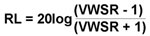
Voltage Standing Wave Ratio (VSWR)
|
|
VSWR is the ratio of the maximum and adjacent minimum wave, expressed in terms of reflection coefficient.
|
|
|
|
|
|
|
VSWR is a real number; a value 1.0 implies a perfectly matched load.
|
|
|
|
|
|
Insertion Loss
|
|
The composite Insertion Loss of a transmission line is determined by the loss associated with the inner and outer conductor, the dielectric medium and characteristic impedance mismatches.
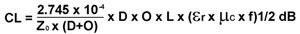
1. Conductor Loss is a function of transmission line dimensions and materials.
|
|
|
|
|
Where:
|
CL
|
- Conductor Loss (dB)
|
L
|
- Conductor length (inches)
|
|
|
|
- Characteristic Impedance (Ohms)
|
|
- Dielectric constant
|
|
|
D
|
- Inside diameter of the outer conductor (inches)
|

|
- Dielectric constant
|
|
|
O
|
- Diameter of the inner conductor (inches)
|
f
|
- Frequency (Hz)
|
|
|
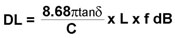
2. Dielectric Losses.
|
|
 |
|
|
Where:
|
DL
|
- Dielectric Loss (dB)
|
|
|

|
- Loss tangent
|
|
|
C
|
- Velocity of propagation
|
|
|
L
|
- Conductor length (inches)
|
|
|
f
|
- Frequency (Hz)
|
|
|
3. Mismatch Loss is a function of reflected energy due to deviations from the characteristic impedance of the transmission line system.
|
|
 |
|
|
|

|
Alpha Center
351 Irving Drive, Oxnard, CA 93030, USA
|
|
©2021 Alpha Products, Inc. All rights reserved.
|
|
|